December 9, 2013

Firewalls and VPN

Network Security and Virtual Private Networks
Objective
The objective of this lab is to study the role of firewalls and Virtual Private Networks (VPNs) in providing security to shared public networks such as the Internet.
Overview
Computer networks are typically a shared resource used by many applications for many different purposes. Sometimes the data transmitted between application processes is confidential, and the application users would prefer that others not be able to read it.
A firewall is a specially programmed router that sits between a site and the rest of the network. It is a router in the sense that it is connected to two or more physical networks and it forwards packets from one network to another, but it also filters the packets that flow through it. A firewall allows the system administrator to implement a security policy in one centralized place. Filter-based firewalls are the simplest and most widely deployed type of firewall. They are configured with a table of addresses that characterize the packets they will and will not forward.
A VPN is an example of providing a controlled connectivity over a public network such as the Internet. VPNs utilize a concept called an IP tunnel—a virtual point-to-point link between a pair of nodes that are actually separated by an arbitrary number of networks. The virtual link is created within the router at the entrance to the tunnel by providing it with the IP address of the router at the far end of the tunnel. Whenever the router at the entrance of the tunnel wants to send a packet over this virtual link, it encapsulates the packet inside an IP datagram. The destination address in the IP header is the address of the router at the far end of the tunnel, while the source address is that of the encapsulating router.
In this lab you will set up a network where servers are accessed over the Internet by customers who have different privileges. You will study how firewalls and VPNs can provide security to the information in the servers while maintaining access for customers with the appropriate privilege.
Procedure
Create a New Project
1. Start OPNET IT Guru Academic Edition ⇒ Choose New from the File menu.
2. Select Project and click OK ⇒ Name the project <your initials>_VPN, and the scenario NoFirewall ⇒ Click OK.
3. Click Quit on the Startup Wizard.
4. To remove the world background map, select the View menu ⇒ BackgroundSet Border Map Select NONE from the drop-down menu Click OK.
Create and Configure the Network
The ppp_server and ppp_wkstn support one underlying SLIP (Serial Line Internet Protocol) connection at a selectable data rate.
PPP DS1 connects two nodes running IP. Its data rate is 1.544 Mbps.
Initialize the Network:
1. Open the Object Palette dialog box by clicking clip_image007. Make sure that the internet_toolbox item is selected from the pull-down menu on the object palette.
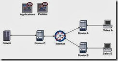
2. Add the following objects, from the palette, to the project workspace (see figure below for placement): Application Config, Profile Config, an ip32_cloud, one ppp_server, three ethernet4_slip8_gtwy routers, and two ppp_wkstn hosts.
a. To add an object from a palette, click its icon in the object palette ⇒ Move your mouse to the workspace and click where you want to place the object ⇒ Right-click to indicate you are done creating objects of this type.
  1. Rename the objects you added and connect them using PPP DS1 links, as shown below:
clip_image009
4. Save your project.
Several example application configurations are available under the Default setting. For example, "Web Browsing (Heavy HTTP1.1)" indicates a Web browsing application performing heavy browsing using HTTP 1.1 protocol..
Configure the Nodes:
  1. Right-click on the Applications node ⇒ Edit Attributes ⇒ Assign Default to the Application Definitions attribute Click OK.
  1. Right-click on the Profiles node ⇒ Edit Attributes ⇒ Assign Sample Profiles to the Profile Configuration attribute ⇒ Click OK.
  1. Right-click on the Server node ⇒ Edit Attributes ⇒ Assign All to the
Application: Supported Services attribute Click OK.
4. Right-click on the Sales A node ⇒ Select Similar Nodes (make sure that both Sales A and Sales B are selected).
i. Right-click on the Sales A node ⇒ Edit Attributes ⇒ Check the Apply Changes to Selected Objects check-box.
ii. Expand the Application: Supported Profiles attribute ⇒ Set rows to 1 ⇒ Expand the row 0 hierarchy ⇒ Profile Name = Sales Person (this is one of the “sample profiles” we configured in the Profiles node).
iii. Click OK.
5. Save your project.
Choose the Statistics
DQ Query Response Time is measured from the time when the database query application
sends a request to the server to the time it receives a response packet.
HTTP Page Response Time specifies the time required to retrieve the entire page with all the contained inline objects.
1. Right-click anywhere in the project workspace and select Choose Individual Statistics from the pop-up menu.
2. In the Choose Results dialog, check the following statistics:
i. Global Statistics DB Query Response Time (sec).
ii. Global Statistics HTTP Page Response Time (seconds).
3. Click OK.
4. Right-click on the Sales A node and select Choose Individual Statistics from the pop-up menu.
5. In the Choose Results dialog, check the following statistics:
i. Client DB Traffic Received (bytes/sec).
ii. Client Http Traffic Received (bytes/sec).
6. Click OK.
7. Right-click on the Sales B node and select Choose Individual Statistics from the pop-up menu.
8. In the Choose Results dialog, check the following statistics:
i. Client DB Traffic Received (bytes/sec).
ii. Client Http Traffic Received (bytes/sec).
9. Click OK and then save your project.
The Firewall Scenario
In the network we just created, the Sales Person profile allows both sales sites to access applications such as Database Access, Email, and Web Browsing from the server (check the Profile Configuration of the Profiles node). Assume that we need to protect the database in the server from external access, including the salespeople. One way to do that is to replace Router C with a firewall as follows:
1. Select Duplicate Scenario from the Scenarios menu and name it Firewall
Click OK.
2. In the new scenario, right-click on Router CEdit Attributes.
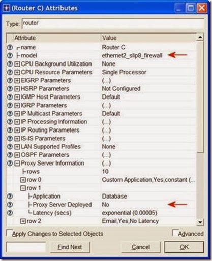
3. Assign ethernet2_slip8_firewall to the model attribute.
4. Expand the hierarchy of the Proxy Server Information attribute ⇒ Expand the row 1, which is for the Database application, hierarchy Assign No to the Proxy Server Deployed attribute as shown:
clip_image011
Proxy Server Information is a table defining the configuration of the proxy servers on the firewall. Each row indicates whether a proxy server exists for a certain application and the amount of additional delay that will be introduced to each forwarded packet of that application by the proxy server.
5. Click OK and then save your project.
Our Firewall configuration does not allow database-related traffic to pass through the firewall (it filters such packets out). This way, the databases in the server are protected from external access. Your Firewall scenario should look like the following figure.
clip_image013

The Firewall_VPN Scenario
In the Firewall scenario, we protected the databases in the server from “any” external access using a firewall router. Assume that we want to allow the people in the Sales A site to have access to the databases in the server. Since the firewall filters all database-related traffic regardless of the source of the traffic, we need to consider the VPN solution. A virtual tunnel can be used by Sales A to send database requests to the server. The firewall will not filter the traffic created by Sales A because the IP packets in the tunnel will be encapsulated inside an IP datagram.
1. While you are in the Firewall scenario, select Duplicate Scenario from the Scenarios menu and give it the name Firewall_VPN Click OK.
2. Remove the link between Router C and the Server.
3. Open the Object Palette dialog box by clicking clip_image014. Make sure that the opened palette is the one called internet_toolbox.
i. Add to the project workspace one ethernet4_slip8_gtwy and one IP VPN Config (see the figure below for placement).
ii. From the Object Palette, use two PPP DS1 links to connect the new router to Router C (the firewall) and to the Server, as shown below.
iii. Close the Object Palette dialog box.
4. Rename the IP VPN Config object to VPN.
5. Rename the new router to Router D as shown:
clip_image016

Configure the VPN:
  1. Right-click on the VPN node ⇒ Edit Attributes.
i. Expand the VPN Configuration hierarchy ⇒ Set rows to 1 ⇒ Expand row 0 hierarchy ⇒ Edit the value of Tunnel Source Name and write down Router A Edit the value of Tunnel Destination Name and write down Router D.
ii. Expand the Remote Client List hierarchy ⇒ Set rows to 1 ⇒ Expand row 0 hierarchy ⇒ Edit the value of Client Node Name and write down Sales A.
iii. Click OK and then save your project.
clip_image018
Run the Simulation
To run the simulation for the three scenarios simultaneously:
1. Go to the Scenarios menu ⇒ Select Manage Scenarios.
2. Change the values under the Results column to <collect> (or <recollect>) for the three scenarios. Keep the default value of the Sim Duration (1 hour). Compare to the following figure.
clip_image020

3. Click OK to run the three simulations. Depending on the speed of your processor, this may take several minutes to complete.
4. After the three simulation runs complete, one for each scenario, click Close ⇒ Save your project.
View the Results
To view and analyze the results:
1. Select Compare Results from the Results menu.
2. Expand the Sales A hierarchy ⇒ Expand the Client DB hierarchy ⇒ Select the
Traffic Received statistic.
3. Change the drop-down menu in the middle-lower part of the Compare Results dialog box from As Is to time_average as shown.
clip_image022
4. Press Show and the resulting graph should resemble the following one:
clip_image024

5. Create a graph similar to the previous one, but for Sales B:
clip_image026

  1. Create two graphs similar to the previous ones to depict the Traffic Received by the Client Http for Sales A and Sales B.
clip_image028

Note: Results may vary slightly due to different node placement.

December 8, 2013

TCP: Transmission Control Protocol


A Reliable, Connection-Oriented, Byte-Stream Service


Objective

This lab is designed to demonstrate the congestion control algorithms implemented by the Transmission Control Protocol (TCP). The lab provides a number of scenarios to simulate these algorithms. You will compare the performance of the algorithms through the analysis of the simulation results.


Overview

The Internet’s TCP guarantees the reliable, in-order delivery of a stream of bytes. It includes a flow-control mechanism for the byte streams that allows the receiver to limit how much data the sender can transmit at a given time. In addition, TCP implements a highly tuned congestion-control mechanism. The idea of this mechanism is to throttle how fast TCP sends data to keep the sender from overloading the network.

The idea of TCP congestion control is for each source to determine how much capacity is available in the network, so that it knows how many packets it can safely have in transit. It maintains a state variable for each connection, called the congestion window, which is used by the source to limit how much data it is allowed to have in transit at a given time. TCP uses a mechanism, called additive increase/multiplicative decrease, that decreases the congestion window when the level of congestion goes up and increases the congestion window when the level of congestion goes down. TCP interprets timeouts as a sign of congestion. Each time a timeout occurs, the source sets the congestion window to half of its previous value. This halving corresponds to the multiplicative decrease part of the mechanism. The congestion window is not allowed to fall below the size of a single packet (the TCP maximum segment size, or MSS). Every time the source successfully sends a congestion window’s worth of packets, it adds the equivalent of one packet to the congestion window; this is the additive increase part of the mechanism.

TCP uses a mechanism called slow start to increase the congestion window “rapidly” from a cold start in TCP connections. It increases the congestion window exponentially, rather than linearly. Finally, TCP utilizes a mechanism called fast retransmit and fast recovery. Fast retransmit is a heuristic that sometimes triggers the retransmission of a dropped packet sooner than the regular timeout mechanism

In this lab you will set up a network that utilizes TCP as its end-to-end transmission protocol and analyze the size of the congestion window with different mechanisms.


Procedure

Create a New Project

1. Start OPNET IT Guru Academic Edition ⇒ Choose New from the File menu.

2. Select Project and click OK ⇒ Name the project <your initials>_TCP, and the scenario No_Drop ⇒ Click OK.

3. In the Startup Wizard: Initial Topology dialog box, make sure that Create Empty Scenario is selected Click Next Select Choose From Maps from the Network Scale list Click Next Choose USA from the Map List Click Next twice ⇒ Click OK.

Create and Configure the Network

Initialize the Network:

The ip32_cloud node model represents an IP cloud supporting up to 32 serial line interfaces at a selectable data rate through which IP traffic can be modeled. IP packets arriving on any cloud interface are routed to the appropriate output interface based on their destination IP address. The RIP or OSPF protocol may be used to automatically and dynamically create the cloud's routing tables and select routes in an adaptive manner. This cloud requires a fixed amount of time to route each packet, as determined by the

Packet Latency attribute of the node.

1. The Object Palette dialog box should now be on the top of your project space. If it is not there, open it by clicking clip_image007. Make sure that the internet_toolbox item is selected from the pull-down menu on the object palette.

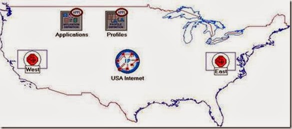
2. Add to the project workspace the following objects from the palette: Application Config, Profile Config, an ip32_Cloud, and two subnets.

a. To add an object from a palette, click its icon in the object palette ⇒ Move your mouse to the workspace ⇒ Click to drop the object in the desired location ⇒ Right-click to finish creating objects of that type.

3. Close the palette.

4. Rename the objects you added as shown and then save your project:

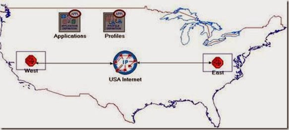
clip_image009

Configure the Applications:

  1. Right-click on the Applications node ⇒ Edit Attributes ⇒ Expand the Application Definitions attribute and set rows to 1 Expand the new row Name the row FTP_Application.

i. Expand the Description hierarchy ⇒ Edit the FTP row as shown (you will need to set the Special Value to Not Used while editing the shown attributes):

clip_image011

2. Click OK twice and then save your project.

Configure the Profiles:

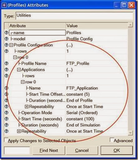
  1. Right-click on the Profiles node ⇒ Edit Attributes ⇒ Expand the Profile Configuration attribute and set rows to 1.

i. Name and set the attributes of row 0 as shown ⇒ Click OK.

clip_image013

The ethernet4_slip8_ gtwy node model represents an IP-based gateway supporting four Ethernet hub interfaces and eight serial line interfaces.

Configure the West Subnet:

  1. Double-click on the West subnet node. You get an empty workspace, indicating that the subnet contains no objects.
  1. Open the object palette clip_image007[1] and make sure that the internet_toolbox item is selected from the pull-down menu.
  1. Add the following items to the subnet workspace: one ethernet_server, one ethernet4_slip8_gtwy router, and connect them with a bidirectional 100_BaseT link ⇒ Close the palette ⇒ Rename the objects as shown.

clip_image015

  1. Right-click on the Server_West node ⇒ Edit Attributes:

i. Edit Application: Supported Services ⇒ Set rows to 1 ⇒ Set Name to FTP_Application Click OK.

ii. Edit the value of the Server Address attribute and write down Server_West.

iii. Expand the TCP Parameters hierarchy ⇒ Set both Fast Retransmit and

Fast Recovery to Disabled.

  1. Click OK and then save your project.

Now, you have completed the configuration of the West subnet. To go back to the top level of the project, click the Go to next higher level clip_image017 button.

Configure the East Subnet:

  1. Double-click on the East subnet node. You get an empty workspace, indicating that the subnet contains no objects.
  1. Open the object palette clip_image018 and make sure that the internet_toolbox item is selected from the pull-down menu.
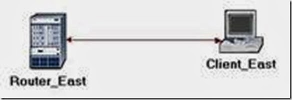
  1. Add the following items to the subnet workspace: one ethernet_wkstn, one ethernet4_slip8_gtwy router, and connect them with a bidirectional 100_BaseT link ⇒ Close the palette ⇒ Rename the objects as shown.

clip_image020

  1. Right-click on the Client_East node ⇒ Edit Attributes:

i. Expand the Application: Supported Profiles hierarchy ⇒ Set rows to 1 ⇒ Expand the row 0 hierarchy ⇒ Set Profile Name to FTP_Profile.

ii. Assign Client_ East to the Client Address attributes.

iii. Edit the Application: Destination Preferences attribute as follows:

Set rows to 1 ⇒ Set Symbolic Name to FTP Server ⇒ Edit Actual Name

Set rows to 1 ⇒ In the new row, assign Server_West to the Name column.

  1. Click OK three times and then save your project.
  1. You have now completed the configuration of the East subnet. To go back to the project space, click the Go to next higher level clip_image021 button.

Connect the Subnets to the IP Cloud:

  1. Open the object palette clip_image018[1].
  1. Using two PPP_DS3 bidirectional links connect the East subnet to the IP Cloud and the West subnet to the IP Cloud.
  1. A pop-up dialog box will appear asking you what to connect the subnet to the IP Cloud with. Make sure to select the “routers.”
  1. Close the palette.

clip_image023

Choose the Statistics

OPNET provides the following capture modes:

All values—collects every data point from a statistic.

Sample—collects the data according to a user-specified time interval or sample count. For example, if the time interval is 10, data is sampled and recorded every 10th second. If the sample count is 10, every 10th data point is recorded. All other data points are discarded.

Bucket—collects all of the points over the time interval or sample count into a “data bucket” and generates a result from each bucket. This is the default mode.

1. Right-click on Server_West in the West subnet and select Choose Individual Statistics from the pop-up menu.

2. In the Choose Results dialog box, choose the following statistic:

TCP Connection Congestion Window Size (bytes) and Sent Segment Sequence Number.

3. Right-click on the Congestion Window Size (bytes) statistic ⇒ Choose Change Collection Mode In the dialog box check Advanced From the drop-down menu, assign all values to Capture mode as shown ⇒ Click OK.

clip_image025

4. Right-click on the Sent Segment Sequence Number statistic ⇒ Choose

Change Collection Mode In the dialog box check Advanced From the drop-down menu, assign all values to Capture mode.

5. Click OK twice and then save your project.

6. Click the Go to next higher level clip_image021[1] button.

Configure the Simulation

Here we need to configure the duration of the simulation:

1. Click on clip_image027 and the Configure Simulation window should appear.

2. Set the duration to be 10.0 minutes.

3. Click OK and then save your project.

Duplicate the Scenario

With fast retransmit,

TCP performs a retransmission of what appears to be the missing segment, without waiting for a retransmission timer to expire.

After fast retransmit sends what appears to be the missing segment, congestion avoidance but not slow start is performed. This is the fast recovery algorithm.

The fast retransmit and fast recovery algorithms are usually implemented together (RFC 2001).

In the network we just created we assumed a perfect network with no discarded packets. Also, we disabled the fast retransmit and fast recovery techniques in TCP. To analyze the effects of discarded packets and those congestion-control techniques, we will create two additional scenarios.

  1. Select Duplicate Scenario from the Scenarios menu and give it the name

Drop_NoFast Click OK.

  1. In the new scenario, right-click on the IP CloudEdit Attributes ⇒ Assign

0.05% to the Packet Discard Ratio attribute.

  1. Click OK and then save your project.
  1. While you are still in the Drop_NoFast scenario, select Duplicate Scenario from the Scenarios menu and give it the name Drop_Fast.

5. In the Drop_Fast scenario, right-click on Server_ West, which is inside the West subnet ⇒ Edit Attributes ⇒ Expand the TCP Parameters hierarchy ⇒ Enable the Fast Retransmit attribute ⇒ Assign Reno to the Fast Recovery attribute.

  1. Click OK and then save your project.

Run the Simulation

To run the simulation for the three scenarios simultaneously:

1. Go to the Scenarios menu ⇒ Select Manage Scenarios.

2. Change the values under the Results column to <collect> (or <recollect>) for the three scenarios. Compare to the following figure.

clip_image029

3. Click OK to run the three simulations. Depending on the speed of your processor, this may take several minutes to complete.

4. After the three simulation runs complete, one for each scenario, click Close ⇒ Save your project.

View the Results

To switch to a scenario, choose Switch to Scenario from the

Scenarios menu or just press Ctrl+<scenario number>.

To view and analyze the results:

1. Switch to the Drop_NoFast scenario (the second one) and choose View Results from the Results menu.

2. Fully expand the Object Statistics hierarchy and select the following two results:

Congestion Window Size (bytes) and Sent Segment Sequence Number.

clip_image031

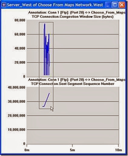
3. Click Show. The resulting graphs should resemble the ones below.

clip_image033

4. To zoom in on the details in the graph, click and drag your mouse to draw a rectangle, as shown above.

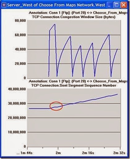
5. The graph should be redrawn to resemble the following one:

clip_image035

6. Notice the Segment Sequence Number is almost flat with every drop in the congestion window.

7. Close the View Results dialog box and select Compare Results from the Result menu.

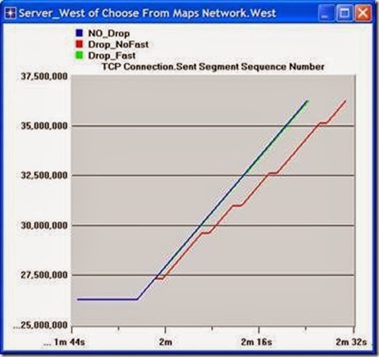
8. Fully expand the Object Statistics hierarchy as shown and select the following result: Sent Segment Sequence Number.

clip_image037

9. Click Show. After zooming in, the resulting graph should resemble the one below.

clip_image039


ATM: A Connection-Oriented, Cell-Switching Technology

The objective of this lab is to examine the effect of ATM adaptation layers and service classes on the performance of the network.


Overview

Asynchronous Transfer Mode (ATM) is a connection-oriented, packet-switched technology. The packets that are switched in an ATM network are of a fixed length, 53 bytes, and are called cells. The cell size has a particular effect on carrying voice traffic effectively. The ATM Adaptation Layer (AAL) sits between ATM and the variable-length packet protocols that might use ATM, such as IP. The AAL header contains the information needed by the destination to reassemble the individual cells back into the original message. Because ATM was designed to support all sorts of services, including voice, video, and data, it was felt that different services would have different AAL needs. AAL1 and AAL2 were designed to support applications, like voice, that require guaranteed bit rates. AAL3/4 and AAL5 provide support for packet data running over ATM.

ATM provides QoS capabilities through its five service classes: CBR, VBR-rt, VBR-nrt, ABR, and UBR. With CBR (constant bit rate), sources transmit stream traffic at a fixed rate. CBR is well-suited for voice traffic that usually requires circuit switching. Therefore, CBR is very important to telephone companies. UBR, unspecified bit rate, is ATM’s best-effort service. There is one small difference between UBR and the best-effort model. Because ATM always requires a signaling phase before data is sent, UBR allows the source to specify a maximum rate at which it will send. Switches may make use of this information to decide whether to admit or reject the new VC (virtual circuit).

In this lab you will set up an ATM network that carries three applications: Voice, Email, and FTP. You will study how the choice of the adaptation layer as well as the service classes can affect the performance of the applications.


Procedure

Create a New Project

1. Start OPNET IT Guru Academic Edition ⇒ Choose New from the File menu.

2. Select Project and click OK ⇒ Name the project <your initials>_ATM, and the scenario CBR_UBR ⇒ Click OK.

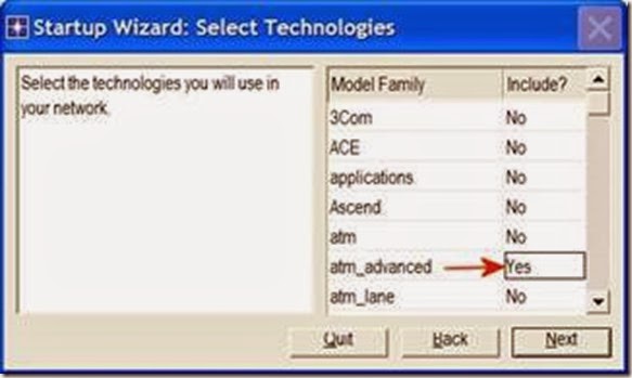
3. In the Startup Wizard: Initial Topology dialog box, make sure that Create Empty Scenario is selected Click Next Select Choose From Maps from the Network Scale list Click Next Choose USA from the maps Click Next From the Select Technologies list, include the atm_advanced Model Family as shown in the following figure⇒ Click Next ⇒ Click OK.
clip_image004

Create and Configure the Network

Initialize the Network:

1. The Object Palette dialog box should now be on the top of your project workspace. If it is not there, open it by clicking clip_image006. Make sure that atm_advanced is selected from the pull-down menu on the object palette.

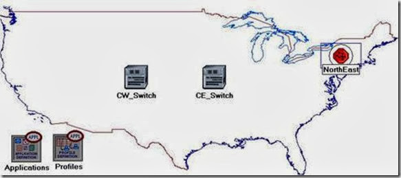
2. Add to the project work space the following objects from the palette: Application Config, Profile Config, two atm8_crossconn_adv switches, and a subnet.

a. To add an object from a palette, click its icon in the object palette ⇒ Move your mouse to the workspace and click to place the object ⇒ Right-click to get out of “object creation mode.”

3. Close the Object Palette dialog box and rename (right-click on the node ⇒ Set Name) the objects you added as shown and then save your project:

PCM stands for Pulse Code Modulation. It is a procedure used to digitize speech before transmitting it over the network.

Configure the Applications:
clip_image008

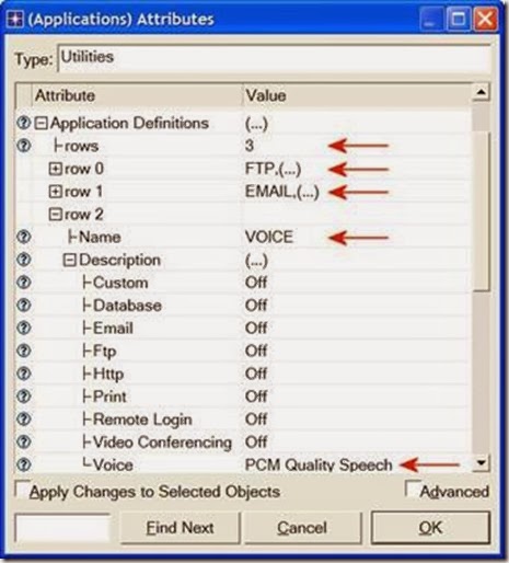
  1. Right-click on the Applications node ⇒ Edit Attributes ⇒ Expand the Application Definitions attribute and set rows to 3 Name the rows: FTP,

EMAIL, and VOICE.

i. Go to the FTP row ⇒ Expand the Description hierarchy ⇒ Assign High Load to FTP.

ii. Go to the EMAIL row ⇒ Expand the Description hierarchy ⇒ Assign High Load to Email.

iii. Go to the VOICE row ⇒ Expand the Description hierarchy ⇒ Assign PCM Quality Speech to Voice.
clip_image010

2. Click OK and then save your project.

Configure the Profiles:

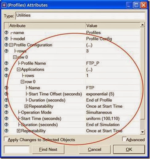
  1. Right-click on the Profiles node ⇒ Edit Attributes ⇒ Expand the Profile Configuration attribute and set rows to 3.

i. Name and set the attributes of row 0 as shown:
clip_image012

ii. Name and set the attributes of row 1 as shown:
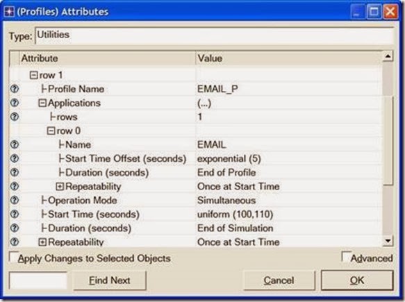
clip_image014

iii. Name and set the attributes of row 2 as shown. (Note: To set the Duration to exponential(60), you will need to assign “Not Used” to the “Special Value”)

⇒ Close the Object Palette dialog box.
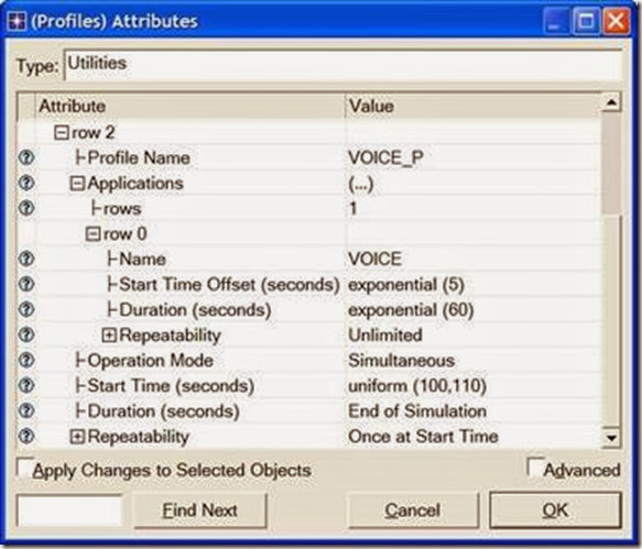
clip_image016

Configure the NorthEast Subnet:

  1. Double-click on the NorthEast subnet node. You get an empty workspace, indicating that the subnet contains no objects.
  1. Open the object palette clip_image006[1] and make sure that atm_advanced is selected from the pull-down menu on the object palette..
  1. Add the following items to the subnet workspace: one atm8_crossconn_adv switch, one atm_uni_server_adv, four atm_uni_client_adv, and connect them with bidirectional atm_adv links ⇒ Close the palette ⇒ Rename the objects as shown.
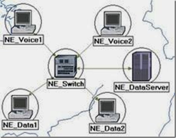
clip_image018

Hint: To edit the attributes of multiple nodes in a single operation, select all nodes simultaneously using shift and left-click; then Edit Attributes of one of the nodes, and select Apply Changes to Selected Objects.

Client Address is the Transport Adaptation Layer (TPAL) address of the node. This value must be unique for each node.

The TPAL model suite presents a basic, uniform interface between applications and transport layer models. All interactions with a remote application through TPAL are organized into sessions. A session is a single conversation between two applications through a transport protocol.

The queue configuration specifies a one-to-one mapping between output port queues and the QoS that they support. A specific queue may be configured to support a specific QoS.

4. Change the data rate attribute for all links to DS1.

5. For both NE_Voice1 and NE_Voice2, set the following attributes:

i. Set ATM Application Parameters to CBR only.

ii. Expand the ATM Parameters hierarchy ⇒ Set Queue Configuration to

CBR only.

iii. Expand the Application: Supported Profiles hierarchy ⇒ Set rows to 1 ⇒ Expand the row 0 hierarchy ⇒ Set Profile Name to VOICE_P.

iv. Application: Supported Services Edit its value Set rows to 1 Set

Name of the added row to VOICE Click OK.

v. Expand the Application: Transport Protocol hierarchy ⇒ Voice Transport = AAL2.

6. For NE_Voice1, select Edit Attributes ⇒ Edit the value of the Client Address attribute and write down NE_Voice1.

7. For NE_Voice2, select Edit Attributes ⇒ Edit the value of the Client Address attribute and write down NE_Voice2.

8. Configure the NE_DataServer as follows:

i. Application: Supported Services Edit its value Set rows to 2 Set

Name of the added rows to: EMAIL and FTP Click OK.

ii. Expand the Application: Transport Protocol Specification hierarchy ⇒ Voice Transport = AAL2.

iii. Edit the value of the Server Address attribute and write down

NE_DataServer.

9. For both NE_Data1 and NE_Data2, set the following attributes:

i. Expand the ATM Parameters hierarchy ⇒ Set Queue Configuration to

UBR.

ii. Expand the Application: Supported Profiles hierarchy ⇒ Set rows to 2 ⇒ Set Profile Name to FTP_P (for row 0) and to EMAIL_P (for row 1).

10. For NE_Data1, select Edit Attributes ⇒ Edit the value of the Client Address attribute and write down NE_Data1.

11. For NE_Data2, select Edit Attributes ⇒ Edit the value of the Client Address attribute and write down NE_Data2.

12. Save your project.

Add Remaining Subnets:

  1. Now you completed the configuration of the NorthEast subnet. To go back to the project space, click the Go to the higher level clip_image020 button.

The subnets of the other regions should be similar to the NorthEast one except for the names and client addresses.

  1. Make three copies of the subnet we just created.
  1. Rename (right-click on the node ⇒ Set Name) the subnets and connect them to the switches with bidirectional atm_adv links as shown. (Note: You will be asked to pick the node inside the subnet to be connected to the link. Make sure to choose the “switch” inside each subnet to be connected.)
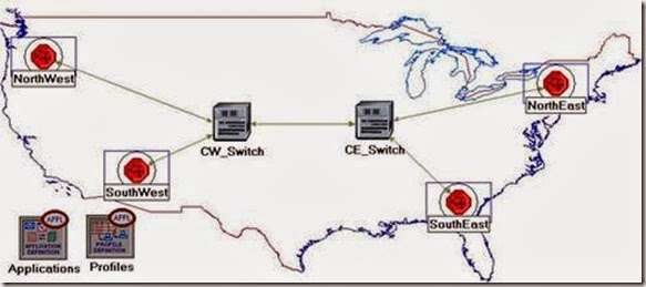
clip_image022

  1. Change the data rate for all links to DS1.

5. Select and double-click each of the new subnets (total four subnets) and change the names, client address, and server address of the nodes inside these subnets as appropriate (e.g., replace NE with SW for the SouthWest subnet).

Hint: To do step 6, you can right-click on any voice station and choose

Edit Similar Nodes. This brings up a table in which each node occupies one row and attributes are shown in the columns.

Follow the same procedure with similar steps in this lab.

6. For all voice stations in all subnets (total of eight stations), edit the value of the

Application: Destination Preferences attribute as follows:

i. Set rows to 1 ⇒ Set Symbolic Name to Voice Destination ⇒ Click on (…) under the Actual Name column ⇒ Set rows to 6 ⇒ For each row choose a voice station that is not in the current subnet. The following figure shows the actual names for one of the voice stations in the NorthEast subnet:

clip_image024

7. For all data stations in all subnets (total of eight stations), configure the

Application: Destination Preferences attribute as follows:

i. Set rows to 2 ⇒ Set Symbolic Name to FTP Server for the one row and Email Server for the other row For each symbolic name (i.e., FTP Server and Email Server), click on (…) under the Actual Name column ⇒ Set rows to 3 ⇒ For each row choose a data server that is not in the current subnet. The following figure shows the actual names for one of the data stations in the NorthEast subnet:

clip_image026

Hint: To do step 8 in a single operation, you can use the right-click menu on any switch to Select Similar Nodes; then Edit Attributes, and check Apply Changes to Selected Objects. This feature does work, even across objects in different subnets.

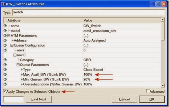
Max_Avail_BW is the maximum bandwidth allocated to this queue. Calls will be admitted into this queue only if they are within the maximum available bandwidth requirement.

8. For all switches in the network (total of six switches), configure the Max_Avail_BW of the CBR queue to be 100%, as shown below, and the

Min_Guaran_BW to be 20%.
clip_image028

9. Save your project.

Choose the Statistics

To test the performance of the applications defined in the network, we will collect one of the many available statistics as follows:

1. Right-click anywhere in the project workspace and select Choose Individual Statistics from the pop-up menu.

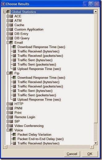
2. In the Choose Results dialog box, choose the following statistics:
clip_image030

3. Click OK.

Configure the Simulation

Here we need to configure the duration of the simulation:

1. Click on the Configure/Run Simulation button: clip_image032.

2. Set the duration to be 10.0 minutes.

3. Click OK. We will be running the simulation later.

Duplicate the Scenario

In the network we just created, we used the CBR service class for the Voice application and the UBR service class for the FTP and Email applications. To analyze the effect of such different classes of services, we will create another scenario that is similar to the CBR_UBR scenario we just created but it uses only one class of service, UBR, for all applications. In addition, to test the effect of the ATM adaptation layer, in the new scenario we will use AAL5 for the Voice application rather than AAL2.

1. Select Duplicate Scenario from the Scenarios menu and give it the name

UBR_UBR Click OK.

2. For all voice stations in all subnets, reconfigure them as follows. (Check the note below for a faster way to carry out this step.)

i. Set ATM Application Parameters to UBR only.

ii. ATM Parameters Set Queue Configuration to UBR.

iii. Application: Transport Protocol Set Voice Transport to AAL5.

3. Save your project.

Note: One easy way to carry out step 2 above is through the network browser as follows:

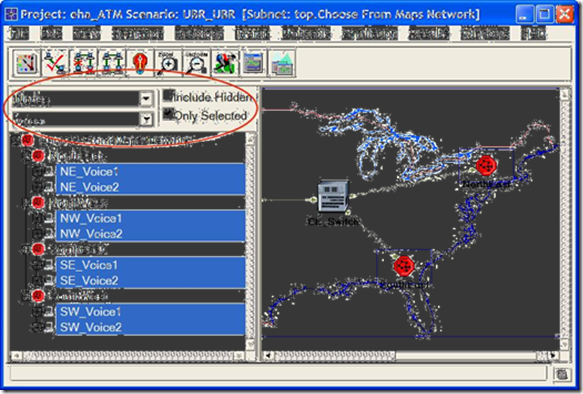
- Select Show Network Browser from the View menu.

- Select Nodes from the drop-down menu, and check the Only Selected check box as shown in the following figure.

- Write voice in the find field and click Enter.

- In the network browser you should see a list of all voice stations selected.

- Right-click on any of the voice stations in the list, select Edit Attributes, and check Apply Changes to Selected Objects.

- Carry out the configuration changes in step 2 above.

- To hide the network browser, deselect Show Network Browser from the View menu.
clip_image034

Run the Simulation

To run the simulation for both scenarios simultaneously:

1. Go to the Scenarios menu ⇒ Select Manage Scenarios.

2. Change the values under the Results column to <collect> (or <recollect>) for both scenarios. Compare to the following figure.

clip_image036

3. Click OK to run the two simulations. Depending on the speed of your processor, this may take several minutes to complete.

4. After the two simulation runs complete, one for each scenario, click Close.

5. Save your project.

View the Results

To view and analyze the results:

1. Select Compare Results from the Results menu.

2. Change the drop-down menu in the right-lower part of the Compare Results dialog box from As Is to time_average as shown.

clip_image038

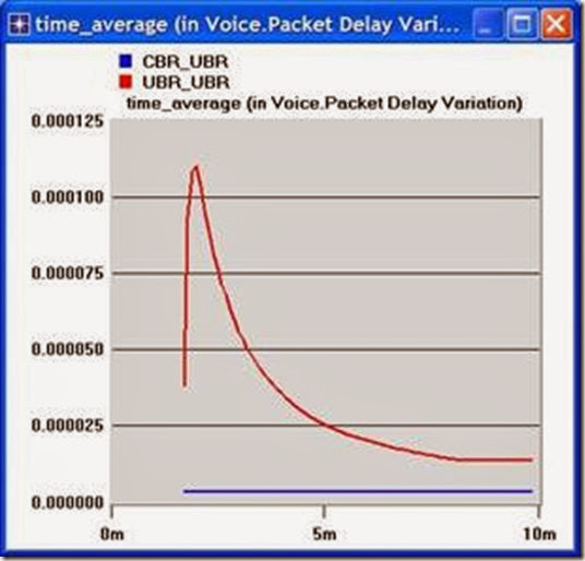
3. Select the voice Packet Delay Variation statistic and click Show. The resulting graph should resemble the one below. (Note: Result may vary slightly due to different node placement.)
clip_image040


C program to Read From a File

#include <stdio.h> #include <stdlib.h> void main() {     FILE *fptr;     char filename[15];     char ch;   ...